Thermal bridges can reduce roof performance even when mineral wool closely fills the spaces between rafters. Timber members and poorly detailed junctions allow heat to pass through more readily than the insulation. Learn how repeating bridges arise and how a continuous layer below the rafters helps reduce their effect.
Thermal bridges at rafters — how do they arise?
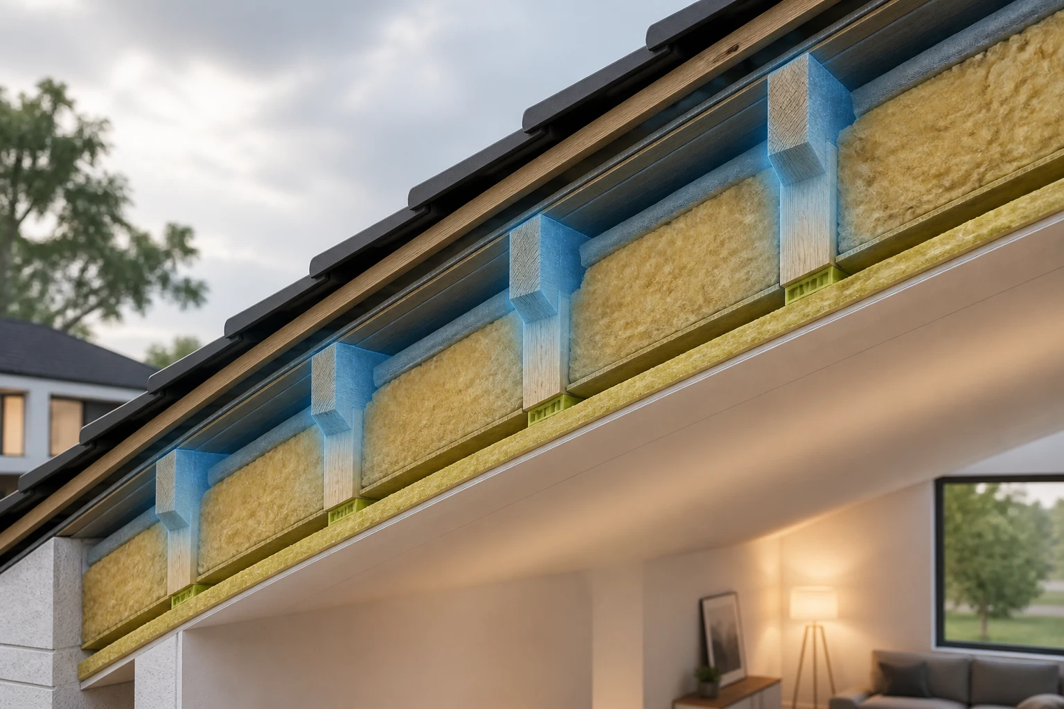
A rafter interrupts the insulation installed between structural members. Timber has different thermal properties from mineral wool, so roof performance depends not only on λD and insulation thickness, but also on the proportion of timber, rafter spacing and structural geometry. Both heat-flow paths must be included in the U-value calculation.
Insulation below the rafters improves continuity
An additional continuous layer of insulation on the inside of the rafters reduces the effect of the timber members and helps maintain continuity at junctions. Its thickness, support framework and fixings should follow the design, since profiles, hangers and services also affect the assembly.
Details that need particular attention
- the junction between the roof slope, wall and wall plate,
- roof window reveals,
- roof corners and valleys,
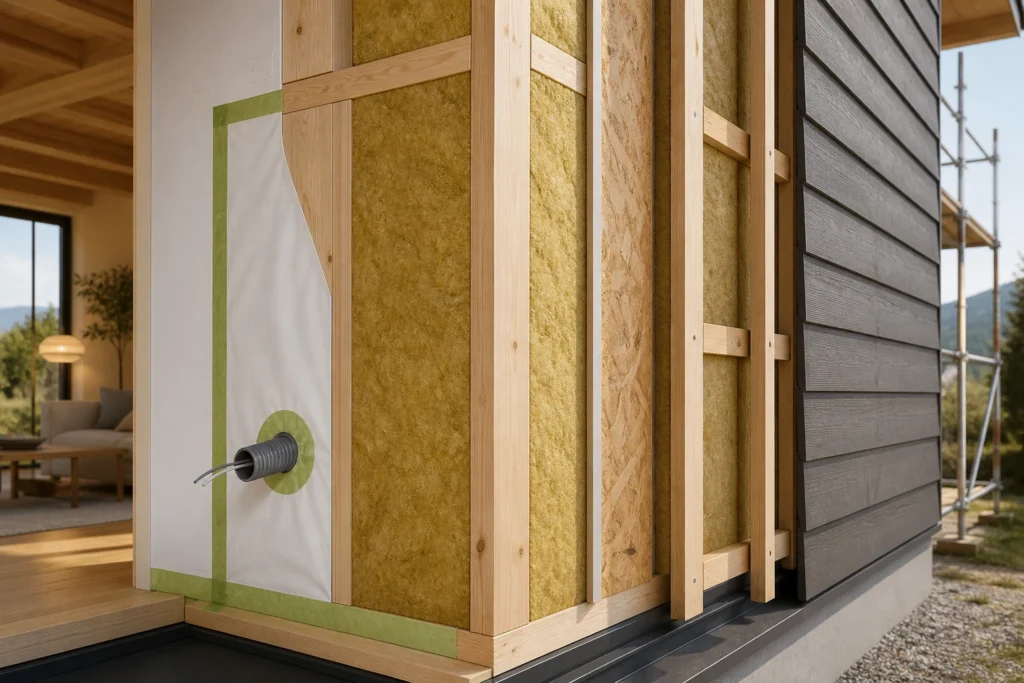
- cable and duct penetrations,
- the junction between the roof and gable wall,
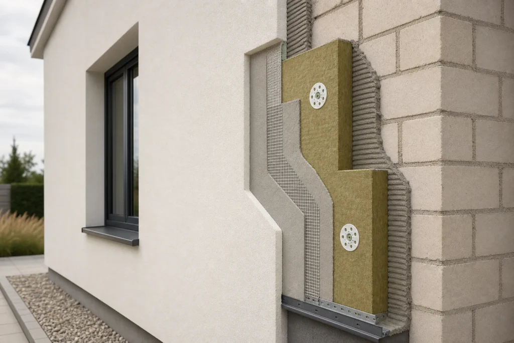
- the connection between roof insulation and external wall insulation.
Consider heat, moisture and airtightness together
Lower local surface temperatures may increase the risk of condensation, but insulation thickness alone does not solve the problem. Continuous insulation, air movement control, a correctly designed layer arrangement and sealed joints are all required. The hygrothermal assessment should reflect the actual construction and the building’s operating conditions.
Explore solutions and products for insulating roof slopes and the spaces between rafters. Pitched roof insulation
Technical reference
U-value limits and requirements for the thermal protection of buildings are set out in the Polish Technical Conditions for buildings. The calculation should reflect the actual geometry of the roof.